


News
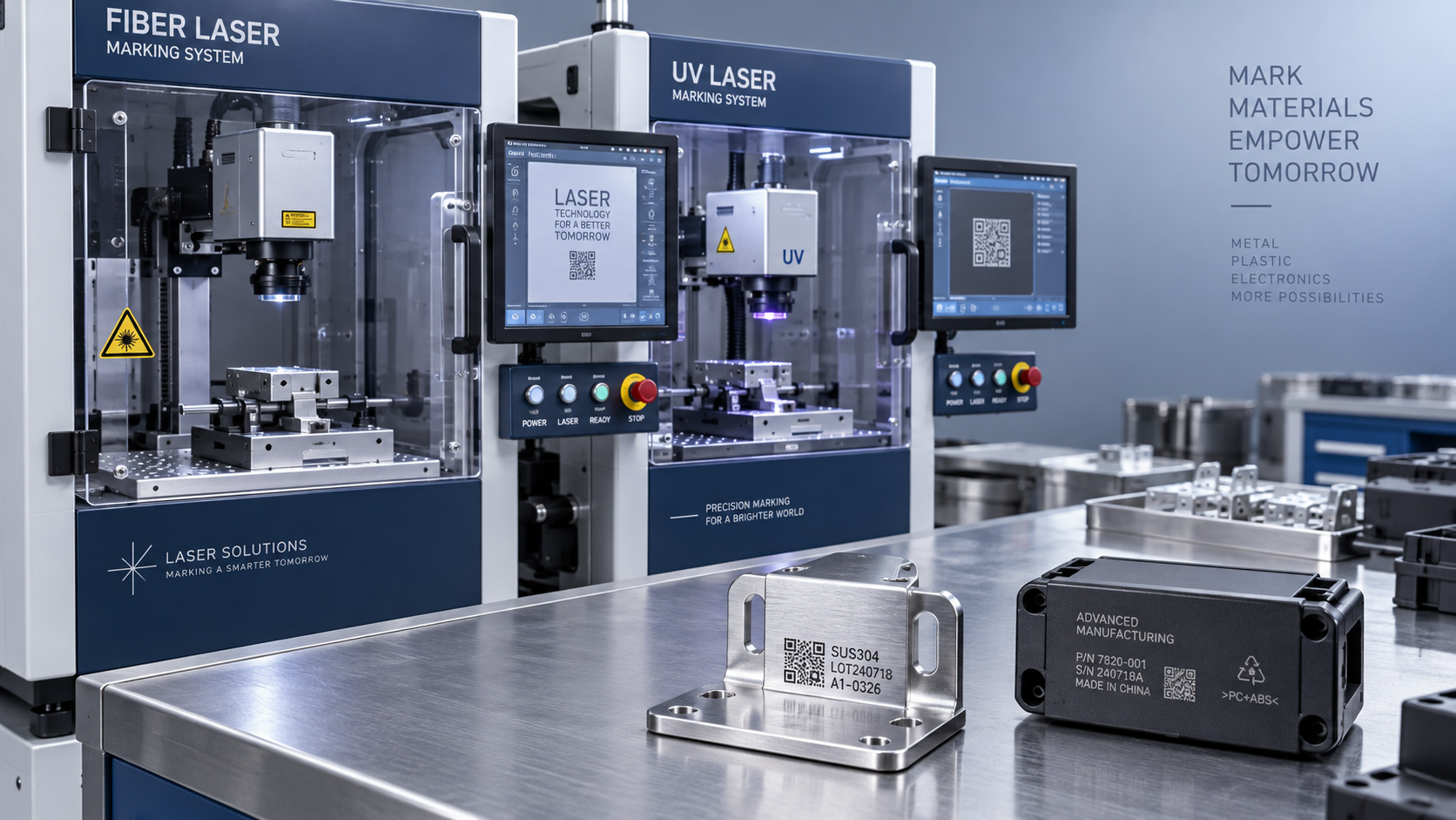
A metal bracket and a molded plastic housing may need the same traceability code, yet respond very differently to the same laser. A setting that produces a sharp mark on steel can melt a polymer surface; a gentle plastic-marking process may take too long to engrave metal. Fiber lasers are usually the first choice for durable metal marking and engraving, while UV lasers are often better candidates for heat-sensitive plastics and small, fine-feature marks. The wrong choice can create unreadable codes, cosmetic rejects, or damage that is not immediately visible.
Choosing between fiber and UV Laser Marking Machines therefore starts with the actual component, not the machine’s wattage. Material formulation, surface finish, required mark depth, and available cycle time determine whether either technology has a usable process window. For mixed metal-and-plastic production, the decisive question is whether one system can meet every requirement reliably—not whether it can produce a visible mark on every sample.
The wavelength difference—and what it does not tell you
Most industrial pulsed fiber marking systems operate near 1064 nm in the near-infrared range. They can deliver the energy needed for metal ablation, surface texturing, coating removal, and some oxidation-based marks. Their usefulness on plastics depends heavily on the resin, pigments, fillers, and laser-sensitive additives. Two parts labeled with the same polymer family can respond differently.
Common UV marking systems operate at 355 nm. The shorter wavelength can support a smaller focused spot with suitable optics, and many polymers absorb UV more readily than near-infrared light. UV processing can involve photochemical effects alongside thermal mechanisms, often allowing fine marks with less surrounding heat damage. However, the familiar description “cold marking” is not a guarantee: excessive pulse overlap or repeated passes can still cause melting, discoloration, or degradation.
Wavelength alone does not determine performance. Pulse duration, pulse energy, repetition rate, beam quality, and lens selection all affect the result. A MOPA fiber source may provide adjustable pulse durations that widen the processing options for certain materials, but it does not automatically replace UV on sensitive plastics. Compare demonstrated processes rather than assuming all machines within either category behave alike.
Metal components: distinguish contrast from engraving
A serial number that only needs to remain readable during assembly is a different task from a recessed identifier that must survive abrasion or later finishing. Before testing, specify whether the mark must change surface color, remove a coating, texture the substrate, or reach a defined depth. “Permanent marking” is too vague to serve as an acceptance criterion.
Bare metal and required depth
Fiber systems are generally the practical starting point for steel, stainless steel, aluminum, titanium, and other industrial metals. The exact mechanism varies. Stainless steel may support dark oxidation-based marks with little material removal, while an engraved mark depends on ablation. Aluminum can require a different strategy to achieve useful contrast, especially when surface texture and viewing angle affect readability.
Where depth is required, assess removal rate, edge quality, debris, and the number of passes. A UV system may mark the metal successfully but struggle to achieve the specified depth within the production takt time. Conversely, excessive fiber energy can leave rough edges or redeposited material that reduces code quality. Maximum laser power is not the same as maximum acceptable production speed.
Surface appearance also does not prove that functional properties are unchanged. On corrosion-sensitive stainless parts, evaluate the selected marking process against the required corrosion performance. On thin components or precision surfaces, check distortion and unwanted changes to roughness or dimensions.
Coated, anodized, or painted surfaces
Here, the laser may be interacting primarily with the surface layer rather than the metal beneath it. Selective removal can produce strong contrast, but the acceptable process window depends on coating thickness, color, and substrate damage limits. Fiber is often effective on anodized aluminum, yet a recipe developed for one finish should not be transferred blindly to another.
UV becomes worth testing when a thin or delicate coating requires precise removal with limited surrounding damage. The acceptance test should establish whether the protective layer may be breached. A readable mark that exposes a corrosion-prone substrate can fail the component requirement even when it passes the visual inspection.
Plastic components: the formulation is part of the specification
A molded housing can look satisfactory under ordinary lighting while its marked area contains softened edges, a raised surface, or local cracking. Such defects matter near sealing faces, snap fits, thin walls, and electrically insulating features. UV is often the better initial candidate when the allowable surface disruption is small, particularly for compact codes and fine text.
Fiber marking remains a valid option for plastics that develop contrast through controlled color change, carbonization, or foaming. Laser-sensitive additives can improve absorption and widen the operating window. But foaming creates a raised structure, and carbonization changes the material locally; neither is automatically acceptable on a functional surface.
Obtain samples representing the production formulation, including color masterbatch, fillers, flame retardants, and any specified laser-marking additive. Testing an unfilled natural resin does not qualify a colored, glass-filled production part. Recycled content and supplier substitutions may also change marking behavior, so material variation belongs in the validation plan.
- For light-colored plastics: assess whether sufficient dark contrast is achievable without charring or unacceptable surface change.
- For dark plastics: determine whether a light mark remains stable after cleaning and wear, rather than relying only on an initial photograph.
- For translucent parts: inspect for subsurface effects, haze, and visibility from the opposite side.
- For thin walls: check deformation and functional integrity, not just the marked surface.
UV should not be treated as universally compatible with plastics. Some formulations produce weak contrast, and others may discolor or degrade under UV exposure. If neither laser produces an acceptable mark, changing the approved formulation or marking location may be more effective than continuing to increase energy.
Small codes and production speed need separate tests
A finer spot can help form small characters, but minimum usable code size is also constrained by material response, scanner accuracy, focus, and the reader. A visually sharp Data Matrix code may still have uneven cell dimensions or insufficient contrast. Use the intended code size and production reading conditions during comparison.
Curved housings and stepped components introduce another limitation: the marking surface may move outside the useful focal range. Larger scan fields also change spot size and energy density. Test at the actual working distance and across the required field, including its edges. Where surface height varies substantially, focus adjustment, suitable fixturing, or three-dimensional marking capability may be necessary.
Compare complete part cycle time, including loading, clamping, focusing, marking, verification, and unloading. A fast laser process may provide little line-level advantage when handling dominates. Conversely, multiple passes needed to protect a plastic surface can become the bottleneck even if the sample looks excellent.
Do not accept a comparison based on equal rated power. Sources with different pulse characteristics and absorption behavior cannot be evaluated that way. Ask each candidate system to produce the same accepted mark, then compare cycle time and operating margin. A faster process is not preferable if small material or focus changes make it unreliable.
A validation sequence that exposes weak process windows
The most useful machine trial produces more than attractive samples. It establishes which settings work, how far they can vary, and what failure looks like. Supply an acceptance specification before the trial so that vendors are solving the same problem.
- Define the mark. State content, dimensions, location, allowable depth or surface change, reading method, durability requirements, and maximum cycle time. Include prohibited effects such as coating penetration or deformation.
- Provide representative parts. Use actual geometry and finish, with relevant material lots and color variants. Coupons can support early screening, but they cannot replace production-shaped components.
- Explore parameter ranges. Vary power, speed, pulse frequency, hatch spacing, focus, and pulse duration where adjustable. Record configurations and identify failure boundaries rather than retaining only the best-looking recipe.
- Verify readability objectively. Use the intended reader and, where required, a suitable code verifier. Check both contrast and geometric quality under representative lighting and orientation.
- Test durability and function. Apply relevant cleaning, abrasion, chemical, or environmental exposure. Inspect surface condition and check affected functional properties.
- Run repeated production-like cycles. Include realistic handling, extraction, fixture tolerances, and operating temperatures. Confirm that results remain acceptable without frequent adjustment.
A robust process has margin around its nominal settings. If a small focus shift or a modest material variation turns a readable mark into melting or faint text, the process needs further development. Saving one successful parameter set is not the same as qualifying a machine.
Ownership costs include the marking cell
Fiber systems are often attractive for metal-focused production because of their processing capability and comparatively straightforward source architecture. UV systems can require a higher investment, but reduced scrap or the ability to mark an otherwise unsuitable plastic may justify it. Without quoted equipment configurations and tested cycle times, a numerical cost comparison would be speculative.
Request maintenance information for the specific source. Depending on design, UV generation may involve frequency-conversion components and thermal-control requirements that influence servicing. Neither technology should be considered maintenance-free. Compare warranty scope, source replacement arrangements, service access, and the cost of production downtime.
The surrounding cell may be as important as the source. Include fixtures, autofocus or height sensing, vision verification, data handling, extraction, and lens protection. Ablating metal coatings or polymers creates airborne material that requires suitable capture and filtration; extraction must reflect the actual substrate and additives.
Both wavelengths require appropriately engineered laser safety controls. An enclosed, interlocked workstation is generally preferable to exposed-beam operation. Reflective metal surfaces, invisible radiation, and service access require a wavelength-specific risk assessment. Do not assume protective eyewear intended for one source is suitable for the other.
Deciding whether one machine can cover both materials
For a production mix dominated by metal engraving, begin with fiber and test the plastics as a separate qualification task. For fine plastic marking with strict limits on surface damage, begin with UV and test whether the metal work remains productive. Neither starting point establishes universal compatibility.
A shared machine is reasonable when both material groups meet acceptance criteria at the required throughput and recipe changes are controlled. Where metal depth demands and plastic damage limits conflict, separate stations may offer better process margin. Require trial results to be delivered with material identification, optical configuration, parameter records, verified mark quality, and complete cycle time. Those records provide a defensible basis for choosing equipment—and for determining whether a later material change requires requalification.
RECENT NEWS
Online Message